

Welcome to my digital home! There are lots of articles you might find helpful buried in this site on topics such as modifying an Alfa Romeo 159, rebuilding a Lotus 7 (Robin Hood 2B), not to mention a ton of stuff on technology in general. It’s all here somewhere, so use the search function or navigate using the menu structure. if you want to talk, reach out via the contact function, I usually do answer!
Random Post Selection
Alfa 159 / ElectronicsFor a while now I have been looking into alternative power solutions for the Alfa due to its power hungry nature that is not helped by the many auxiliary systems I have added over time.
For the most part, the stock battery can cope just fine, but I have always wondered about the use of capacitors and what real value they hold. In years gone by, the capacitors you could get hold of were simply not that useful. A 1 Farad 12v capacitor like you would use in an car audio installation was simply too expensive and had far too little power storage.
One reason I had been considering capacitors was not for power storage but for the side effect of cleaning up the overall noise introduced by the power system in the car. This would serve to improve the overall sound quality of the entire system as well as benefit all electrical systems with a cleaner supply. A good explanation and test is here:
https://youtu.be/T9mlvbF0flM
Capacitors have come on a long way though and the new generation of “Super” or “Ultra” Capacitors are starting to become a viable alternative to a battery in a car. Because of this, I thought it only sensible to buy some parts and see what it was all about 🙂
Here is a video of a car replacement battery using 6x 2.7v, 500F super capacitors to show you what I mean:
Obviously starting the car and providing long term, offline power for the systems when its not running are two different things, so if you seriously wanted to replace your traditional battery you would need a hybrid solution that combined batteries with capacitors.
I’ll be looking into that next 😉
Super capacitors come in a few common shapes and sizes but by far the cheapest for the power are the common 2.7v 500 farad units. To hit the target voltage I needed (12-14v) I needed a few wired in series to increase the overall voltage. Fortunately this is a common solution as its a typical voltage used in solar installations.
Wiring the capacitors in serial actually decreases the overall farads of the bank, so 6 x 2.7v = 16.2v but the farads are divided by 6 to give you 83.333F. You could add a number of additional banks in parallel to bring the farads back up, but it starts to get a bit big then and you would be better looking into a different style capacitor. such as the Maxwell Ultra 2.7V 3000F, 6 of which would deliver a 16.2v 500F pack !
Also, a point of note is that even though the planned bank has a capacity of 16.2v it will only operate at the voltage its charged too, so if the car charges at 13.5v then the bank will be charged to 13.5v. Its also important to balance the load across a serialized bank of capacitors to prevent damage. Fortunately due to the commonality of the target bank design, a balance board was readily available:
The plan was to build a 12v 83 farad bank that would act as a power reserve for the bass amplifier in the boot as this would be a good starting point and bolster the overall power system on easily accessible, existing 4AWG wiring
I first bought a few common, cheap and easily accessible parts off ebay:
6 x Green-Cap (Black) Super Farad Capacitor Parallel Battery 2.7V 500F 35*60MM @ 26.99
6 String 2.7V Super Capacitor Protection Balancing Board 100F – 500F 240x40mm @ 8.75
10 rubber lined 35mm pipe clamps @ £7.29
8 AWG power cable with in line fuse holder and fuse @ 4.99
So for less than £50 I had everything I needed for the experiment. I could have bought a pre-made board with unknown capacitors on for about £26 but I have read a few things about the capacitors being junk so went for a known good brand and DIY.
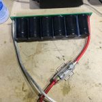
I first assembled the capacitor bank with the balance board to achieve the target solution. Hot gluing the capacitors to the board before soldering them to make sure the finished unit was as solid as possible. It took some real heat on the iron to get the solder flowing, especially soldering in the 8AWG wires.
I soldered the 8AWG cables directly to the board to ensure maximum power transfer:
Once the bank was ready I used the pipe clamps to install the unit in a free space within the amp enclosure and connected it to the positive and negative 4AWG distribution blocks I already had in place from the original installation of the enclosure:
I must admit, I was extremely worried when I first connected the fuse that it would just explode in my face, so it was a tentative and careful moment! Some people recommend installing a resistor inline initially to slow charge the capacitors and protect the systems in between, but as I was on a 4AWG connection direct to the battery I was not worried about the charge / discharge issues.
They did make a fizzing sound for a few seconds when they took there initial charge but I was stood by with a fire extinguisher!
Once the fizzing stopped and nothing looked like it wasd going to explode I checked the units for discharge / earth shorts and also for temperature. As everything was ok, I decided to start the car and run the amp.
The car started quicker than normal so clearly the extra high current supply had already made an impact on the overall electrical system. Its actually possible to start and run an normal engine on a bank of capacitors like this and replace the battery with them as can be seen in one of the videos at the top of the page. Although for the Alfa, I would need a larger bank with more capacity as the 2.4 is a bit of a power hungry beast!
I ran a Bass test loop to get the amp hot and push the sub to its limits for 30 minutes. The amp got very hot as expected but the capacitors only got a little warm which is great as if they got very hot that would be a problem.
Once it was all back together you could hardly notice the upgrade unless you looked very closely at the vent holes!
All in all this was a great upgrade and I am definitely going to explore more super capacitors in the engine bay in some sort of hybrid battery/capacitor solution next!Related Images: [...]

GeneralThe Problem:
Ok, so anyone who has worked with sound equipment before would have been greatly disappointed shortly after taking the M-Audio Xponent out of the box. Essentially, it’s a bit crap. The main bug-bears are the faders, often referred to as being made by “Fisher Price”.They are loose, and generally feel nothing like a proper mixer, so anyone used to using pro audio equipment is going to feel short changed (I know I did!). That said, once you get over them, and there are some tricks you can apply to make them feel less annoying, the other primary bug-bear is Torq. This software can only be described as an epic fail! I gave it a shot, I persevered with it for a long time, and have come to the conclusion that its beat detection engine was programmed using chaos theory.
I have mixed on many different platforms, decks (belt and DD), CDJ’s (from first gen to modern) and midi software from TraktorScratch V1.0 through to the usual suspects of today. What all of these platforms allow you to do is beat match with little effort if you’ve got a good ear. Torq on the other hand, seems to want to fight this process and in my own experience, creates a clinical/harsh environment to align beats without getting nasty overlay (beat on beat cancelation). If you persevere I am sure you can personally compensate for this and actually become good at “mixing with Torq” but IMO I don’t think it appropriate to change my mixing style after 20 years just to accommodate crap software.
This problem brings us to the solution I have discovered. I don’t take credit for pulling this together, many people better than me have toiled long and hard to make this work and have done some excellent work on the subject. All I wanted to do was have a rant, show you how easy it is to make the Xponent better and then credit those who did the work.
The Solution:
Native Instruments have invested a lot of time and energy into refining the Traktor product to what it is today. I have used different iterations of it since Scratch v1.0 (the first ever version) and it just keeps improving! The most recent version is Traktor Pro V1.x, I am using 1.2.4 and it is truly phenomenal. I won’t go into it in too much detail, but will say this much, its intuitive, just like it should be, has some amazing effects available out of the box and “just works perfectly” What more could you ask for?
Of course, Despite the Xponent being a Midi Control Surface and a Sound Card, it’s been locked into Torq to proliferate the spread of the evil program, but, there is a way you can break out of this and turn your midi control surface back into a programmable 2-way midi surface like any other. It’s actually quite simple:
While you switch the device on, press and hold the number 2 Queue button + the Lock Button on the left deck. It’s that simple, hold them till it’s all booted up, and to check its worked, press any button, if it lights up then fades away, it’s not worked and you need to power off and try again. If it does not light up, you’re in business and you have a midi control surface ready to use with any Digital DJ software you want!
At this stage you have a couple of options, start mapping the buttons yourself or grab a map that has already been put together. Personally, I like to short-cut things, so I would grab a predesigned map. After a good look around and a few failed starts, I found a mapping from HolyCT based on the work of DJ Kad listed in the NI Forums. It is amazing! It has all the mappings you would want, full documentation and even a browser mode so you can use the jog wheels to browse your track lists without the keyboard and mouse! It makes use of the X/Y Pad and is IMO a very well put together map for the Xponent.
Bringing the good features from the Xponent to a well written and user friendly piece of software like Traktor Pro, is a marriage made in heaven! I am truly blown away with the usability and playability of the combination, and it has convinced me to stick with my Xponent for the time being. It may not be the best controller in its class, but it has some cool features and once you get used to the faders, it’s not all bad!
Related Images: [...]

InfoSecSo here we are again, a few months on, and just when so many were licking their wounds after the last infection, along comes another. Guess what, if you had your eyes shut my sympathy is not going to be that forthcoming!
Malware has come along way since its anarchistic pre-pubescent beginnings, and is now a fully fledged teenager, displaying all the fire, passion and unpredictability you would expect from one. Once upon a time, you could be sure your malware was simple in its intention, written by an unorganised person or persons, with the typical agenda of notoriety or malicious damage. Although bad, quite easy to deal with.
Modern malware however is a whole new ball game. Written to order, with a menu of “features” available from stealing data to placing a sleeper inside the system, all with standard issue mass infection mechanisms anti malware detection programming, the latest in self defence techniques and with the underlying drive of a typically well organised or at least very motivated source.
Yet despite this significant step change in what we are seeing as the attack, as a world of experts I am still not seeing a change in the controls, strategies or defence tactics of many organisations. This I find astounding. How anyone who is considered a responsible person in an organisation can sleep at night thinking that a firewall and a few layers of Anti-Virus is going to cut it as the total form of protection is seriously miss-informed. Equally, those companies out there pedalling the silver bullets of the security world ” ultimate anti-malware solution (TM)” are doing nothing but compound a problem that will continue to evolve and get more sophisticated.
The simple fact is that ANY malware solution on the planet today from any vendor works on the same detection methods. They look for something they have seen before or something that looks like something they have seen before and block it, It’s that simple. And for that reason alone, you cannot rely on that control alone as the only form of defence. Equally, the firewall and all that other perimeter based paraphernalia you invested in, don’t get me wrong, all well and good, but its not going to stop this stuff. Why? Web 2.0, Social Networking, Unified Communications, Chat, Mail, you name it. Any medium of communication that can facilitate the transfer of a file, and that includes just good old browsing of the web, will bring malware to your door, invited in so to speak, through all that perimeter protection, and straight to the desktop.
The truth is, the only way to protect yourself against this stuff is to stop thinking it’s “the good old days” and get with the times. The only way you’re going to stand a chance of surviving one of these incidents is by thinking about the entire control landscape and how they interact with each other. A good model for this is Defence in Depth as that provides a very good method of visualising the controls at each layer of your environment and allows you to map attacks through the controls to see if they would be successful or not.
This simple visualisation strategy can bring value beyond your wildest dreams, giving you the opportunity to stop, think and adjust what you’re doing, justify investment, demonstrate control and rationalise spend. All very important concepts for the times. There is a world of products, vendors control choices and equipment with pretty flashing LED’s on it. The only way to figure out which ones will help you is to understand what you have, what you need and why.
Related Images: [...]
InfoSecIf your planning on using Linux in a hostile environment, i.e. the Internet! then its worth thinking about some simple little tweaks to the TCP/IP stack in conjunction with some funky firewall madness to keep your box your own, and not end up “owned” too quickly!
Lets start with the TCP/IP stack. There are a number of quick easy wins here that can help defend against attacks through making the default behaviours of the stack more in-line with what we would like:
echo "1" > /proc/sys/net/ipv4/conf/eth0/rp_filter
echo "0" > /proc/sys/net/ipv4/conf/lo/rp_filter
echo "1" > /proc/sys/net/ipv4/conf/all/log_martians
echo "0" > /proc/sys/net/ipv4/conf/lo/log_martians
echo "1" > /proc/sys/net/ipv4/icmp_ignore_bogus_error_responses
echo "1" > /proc/sys/net/ipv4/icmp_echo_ignore_broadcasts
echo "0" > /proc/sys/net/ipv4/icmp_echo_ignore_all
echo "0" > /proc/sys/net/ipv4/conf/all/accept_source_route
echo "0" > /proc/sys/net/ipv4/conf/all/send_redirects
echo "0" > /proc/sys/net/ipv4/conf/all/accept_redirects
echo "0" > /proc/sys/net/ipv4/conf/all/secure_redirects
echo "1" > /proc/sys/net/ipv4/ip_dynaddr
echo "10" > /proc/sys/net/ipv4/tcp_fin_timeout
echo "1800" > /proc/sys/net/ipv4/tcp_keepalive_time
echo "15" > /proc/sys/net/ipv4/ipfrag_time
echo "2048" > /proc/sys/net/ipv4/tcp_max_syn_backlog
echo "32768 61000" > /proc/sys/net/ipv4/ip_local_port_range
echo "2" > /proc/sys/net/ipv4/tcp_synack_retries
Now, that little lot above needs some caveats. Firstly, use at your own risk! Secondly, As per usual, you often get a small performance hit when you start getting more secure, so test each tweak fully before you go into production. Once your happy with the ones you like, add then to your /etc/rc.local or other start up file of your choice.
The next step is to use iptables to help deal with dodgy looking traffic.
Step 1, set-up a bunch of new chains:
$IPTABLES -N CHECK_FLAGS
$IPTABLES -N ALLOW_ICMP
$IPTABLES -N SRC_EGRESS
$IPTABLES -N DST_EGRESS
Step 2, now lets get those chains to do something useful:
$IPTABLES -A CHECK_FLAGS -p tcp --tcp-flags ALL FIN,URG,PSH -m limit
--limit 5/minute -j LOG --log-level $LOG_LEVEL --log-prefix "NMAP-XMAS:"
$IPTABLES -A CHECK_FLAGS -p tcp --tcp-flags ALL FIN,URG,PSH -j DROP
$IPTABLES -A CHECK_FLAGS -p tcp --tcp-flags SYN,RST SYN,RST -m limit
--limit 5/minute -j LOG --log-level $LOG_LEVEL --log-prefix "SYN/RST:"
$IPTABLES -A CHECK_FLAGS -p tcp --tcp-flags SYN,RST SYN,RST -j DROP
$IPTABLES -A CHECK_FLAGS -p tcp --tcp-flags SYN,FIN SYN,FIN -m limit
--limit 5/minute -j LOG --log-level $LOG_LEVEL --log-prefix "SYN/FIN:"
$IPTABLES -A CHECK_FLAGS -p tcp --tcp-flags SYN,FIN SYN,FIN -j DROP
$IPTABLES -A ALLOW_ICMP -p icmp --icmp-type echo-reply -j ACCEPT
$IPTABLES -A ALLOW_ICMP -p icmp --icmp-type destination-unreachable
-j ACCEPT
$IPTABLES -A ALLOW_ICMP -p icmp --icmp-type echo-request -j ACCEPT
$IPTABLES -A ALLOW_ICMP -p icmp --icmp-type time-exceeded -j ACCEPT
for SRCNET in $EGRESS_NETS; do
$IPTABLES -A SRC_EGRESS -s $SRCNET -j DROP
done
for DSTNET in $EGRESS_NETS; do
$IPTABLES -A DST_EGRESS -d $DSTNET -j DROP
done
Step 3, Apply the prior two steps to your input, forward and output chains as needed:
$IPTABLES -A $CHAIN -i $EXT_INT -j SRC_EGRESS
$IPTABLES -A $CHAIN -i $EXT_INT -j DST_EGRESS
$IPTABLES -A $CHAIN -i $EXT_INT -p icmp -j ALLOW_ICMP
$IPTABLES -A $CHAIN -i $EXT_INT -p tcp -j CHECK_FLAGS
Variables. In all of the above, variables are used to save typing!, here are some of the important variables, the rest are fairly self explanatory:
EGRESS_NETS="
172.16.0.0/12
224.0.0.0/4
240.0.0.0/5
14.0.0.0/8
169.254.0.0/16
172.16.0.0/12
192.0.2.0/24
192.88.99.0/24
192.18.0.0/15
0.0.0.0/8
"
What we have just done is setup some new chains, apply some filters that can identify dodgy looking traffic and do something useful with it (limit it rather than drop it, as we don’t want to arouse suspicion with our attackers). Then apply all that nice Packet Mangling to each of our primary chains.
I provide all of this advice for free, with no guarantees, any use of the above code should be with full testing prior to its use in a production environment. Enjoy!
Related Images: [...]
InfoSecOpen post to see coverage:
North West Insider – August 2007 – IT Security
North West Insider – August 2008 – BERR Survey
Related Images: [...]
General…what is it about working from home that makes life so much easier? I treasure my days in the “home office” as they give me opportunity to catch up on all that has evaded me for so long! I find at least 1 day a week keeps me ahead of the game and on top of the workload.
Related Images: [...]

LiveMixesIts been a long time coming, but here it is… a fresh mix on a totally new rig, so excuse the flaky mixing 🙂
https://jabawoki.com/wp-content/mp3/Jabawoki_Rolling_House_Beats_15082009.mp3
Podcast: Play in new window | Download
Related Images: [...]
InfoSecI was recently asked to comment on the new Chip & Pin attack created by Prof Ross Anderson from Cambridge University. In my original comment released to the press I make an assertion in relation to a change in process that “breaks the circuit” of this attack – see below:
Jay Abbott, director in charge of Threat & Vulnerability Management, PricewaterhouseCoopers LLP (PwC), said:“Essentially, what the scientists have come up with is a very effective and simple way of exploiting weaknesses in the system.
However, it is important to bear in mind that the fraud requires a very specific scenario to become effective.
“A simple process change by the retailer of asking for the card holder to hand over the card would break the circuit, although this isn’t always possible as sometimes the card reader is fixed to a point on the other side of the counter.
“At present, the customer is accountable for the fraud as banks argue that PIN verified transactions are secure. Given this attack demonstrates a clear method of bypassing the PIN system, this assertion by the banks stands on shakier ground.”
With the original comment came a caveat, which as you would normally expect, was not quoted by the media, this caveat was that the process change suggested brought with it the opportunity for cards to be skimmed, which was in fact one of the original reasons behind the Chip & Pin changes. In fact, the change works in the favour of the retailer rather than the consumer, however, before you hang me, allow me to demonstrate the rationale behind this.
Consider first that Chip & Pin is in fact “two factor” authentication, which anyone in the security business will explain is more secure than “one factor” authentication. The first factor is the card itself or the “chip” in this instance, the second factor is the “Pin” which in this context operates as a pass code. Given both elements are authenticators in their own right, both are required, and as such any attack must include them both. The attack designed by Prof Ross Anderson targets the Pin aspect of the authentication, and relies on the original card accessed through a series of technology components that have to be connected together in some way. The method shown in this attack makes use of concealment to hide these components on the person of the attacker, and relies on a custom built “attack” card with wires hidden up the sleeve of the attacker, back to the other components involved. The obvious way to therefore detect and prevent this attack at the retailer is by separating the card from the attacker, thus showing the wires and revealing the ruse.
The cloning of cards must be treated separately as the current methods of cloning (that I am aware of at this point in time) only create “yes cards” which would not work in this attack scenario as they are not true copies and would be detected by the PoS equipment as fraudulent. As I understand it, there is no economically viable way of cloning Chip & PIN Cards effectively at this time. Any cloning would still focus on the magnetic stripe data, which can be easily cloned, but is not accepted by the retailers (usually) when a Chip & PIN card is presented. This of course is at the discretion of the retailer and out of the control of the consumer or the banks.
This brings us to the counter argument, specifically in relation to the increased risk of your card getting skimmed/cloned by the retailer when you hand it over. Een if it were viable to clone the chip cards, given that a card skimmed by a retailer would typically not get the pin as well (this of course is not always the case), using the now cloned card would have to make use of Prof Ross Anderson’s attack method, which if the aforementioned process change was implemented, would not work, so in effect increasing the risk of cloning, but decreasing the risk of a successful attack using the cloned card and “breaking the circuit”.
This of course relies on the premise that the use of the cards magnetic strip is in fact not viable, and therefore if anything, reinforces the use of Chip & PIN ironically. Of course in real life the Magstrip is regularly used, but that, again is outside the scope of this discussion and considered irrelevant in the face of the specific discussion around Prof Andersons attack.
There is always of course the argument for using a small form factor wireless transmission device to remove the need for wires, but given the form factor of a credit card and the inability to alter this form factor without raising suspicion, I am personally unsure that significant enough range for a TX/RX comms loop could be achieved given the power that could be implemented into a credit card sized device.
Again, in my original comments to the press I clearly stated that the system needed to be fixed, and that the attack was effective, so this is not me suggesting that we should brush this under the carpet, in fact it is simply looking at what we can potentially do NOW to protect the system, while its eventual upgrade is debated and planned.
Don’t forget, in this context I am just as much of a concerned consumer as you.
Related Images: [...]

Alfa 159Before I even started this project, I spent quite a lot of time figuring out potential box sizes and planning the acoustics of the project. The overall goal was maximum SQ & Power balance with the least boot space loss possible! No mean feet to achieve.
I opted to retain the stock OEM head unit rather than go for an after-market double-din one as I wanted the overall look and feel of the car to remain normal, while improving the audio characteristics and overall frequency response. In order to achieve this I made use of an Audio control LC2i active, line level converter. A unit from the USA that is very special and literally takes speaker level outputs up to 400W RMS and then runs them through a series of electronic clean-up routines to get a perfect line level out for the sub-woofer, than can also be controlled by a remote gain control, and a perfect 2 channel full range output for a mid amp (to be utilised in a further project).
This unit combined with an Infinity KAPPA Perfect 12 VQ (M3D) sub-woofer and an Alpine MRV-420 amplifier I already had was all I needed to put a little boom back into the boot!
” order_by=”sortorder” order_direction=”ASC” returns=”included” maximum_entity_count=”500″]
Related Images: [...]
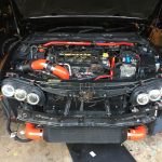
Alfa 159Part of any major power upgrade includes a Front Mount Intercooler conversion to enable the maximum airflow through the compression system, while maximising the cooling opportunity.
The stock intercooler on the 159 is quite restrictive and behind several radiators limiting good airflow to it and also has very restrictive ports for the airflow in and out of it. All due to size and placement options at the factory.
The stock pipework has an ID of 60-63mm so isn’t exactly huge, but is good enough for 3.5-4bar. Its the intercooler that could use a bit of an upgrade!
Once the stock intercooler is removed, all of the other radiators can shuffle around so that it goes (from the engine to the front of the car) Water Rad > Air Con Rad > Oil Rad > Power Steering Rad. All of these items clip to each other so removing the stock intercooler just allows you to put them all back in a different order without any further mods. You will likely need to have the aircon re-gassed and refill the cooling system as doing this without disconnecting those systems is extremely difficult!
An optional upgrade is to remove the stock oil cooler and move that to a larger MOCAL unit located where the stock intake is, but this requires removal of the stock intake and all associated pipework and replacing with something like a BMC-CDA or Cone filter under the bonnet like I have done.
In terms of the parts needed for this conversion, it isn’t that many. Firstly, you need the right sort of intercooler, cheap and efficient! Fortunately, the JDM scene has us covered! They have a standard sized unit that has a 600x300x76mm core that is used in big power Supra and GTR upgrades. Its readily available on ebay for less than £100 delivered.
Make sure you buy the “bar and Plate” type rather than the “tube and fin” ones. The bar and plate type have additional internal structure designed to create turbulence in the airflow and maximise the cooling efficiency.
One thing I will say about these intercoolers; is they do not age well. While they turn up very shiny and polished, after about 2-3 months on the front of the car they go a horrible grey pitted colour that is quite unsightly! I therefore do recommend getting it painted black to help create the stealth look. Of course adding a layer of paint will reduce the efficiency slightly so make the layer as thin as possible.
There are arguments for and against painting the intercooler here:
For:
Against:
While the science is compelling, from experience of running the same setup painted and unpainted, there is nothing in it! I see extremely efficient cooling even with it painted black!
This unit, once bought, needs to be mounted. Fortunately, due to the shape of the 159/Brera there is a huge space up front where this can live with ease! I have designed some brackets that attach directly to the lower sub-frame and provide a mount for this, or any other intercooler. You can get these brackets made up at any local machine shop for £20-30.
The design can be downloaded free of charge:
Once its mounted on the lower sub frame its very solid, but you will need to make some custom tie bars for the top that secure it to the front crash bar. I used some 1mm steel I had lying around and just cut and bent it to shape:
The Intercooler has M8 sockets welded onto it so you will need 4 x M8 bolts @ 12-14mm long to mount it to the brackets and the brackets will need 4 x M8 @ 50-55mm long to go through the lower sub frame.
The pipework is custom, so while I can tell you what bits you need, its up to you to measure and cut them! I strongly recommend watching this video on how to cut silicon pipes before starting:
You are going to need the following bits:
Hot Side (pre cooler)
63mm Joiner (102mm long)
63 – 76 @90 degree reducer elbow
Cold Side (post cooler)
60mm Joiner (102mm long)
60 – 63 @45 degree reducer elbow
63 mm joiner (102mm long)
63 – 76 @90 degree reducer elbow
Mishimoto Constant Tension T-Bolt Clamps
6 x 2.75″ (for the 3 x joins)
2 x 3″ (for the FMIC)
Mikalor W2 Stainless Steel Clamps
1 x 49-63mm (Cold side metal intake pipe)
1 x 55-59mm (Hot side turbo connection)
I can recommend ASH in the UK for the pipes and the joiners, I used them and they are great quality. They are on ebay here: http://stores.ebay.co.uk/autosiliconehosesoutlet/
Do not underestimate the clamps or the joiners! I have tried several different types of both and have had reliability issues resulting in boost hoses popping off at the most inconvenient times! Spend the money, get the best possible parts.The Mishimoto clamps are the best I have seen and provide an extremely good clamp with a system that allows for heat expansion and contraction without sacrificing grip.They dont make constant tension clamps small enough for the connections on the turbo or metal intake so I suggest using Mikalor clamps instead. A very strong clamp just without the heat expansion capability.
You can buy the clamps direct from Mishimoto or the usual ebay sources.
The ASH joiners have very significant insertion into the pipes so you can get lots of grip with the clamps and minimise potential movement that can work a join loose over time!
I have used other joins in the past and they have failed repeatedly, to put that in perspective, take a look at the difference between a popular silicon joiner and the ASH one:
The hot side of the FMIC only needs a single 90 reducer and can be joined directly to the OE pipe with a 63mm joiner.
On the hot side you need to trim back the 90 reducer on the 63 side, and join that to the 63 side of the 45 reducer. This will also need to be cut back and the stock pipe will need to be cut back also. These are the only three cuts you need to make but measure twice and cut once! The 60 side joins to the stock pipe where you cut it as its slightly narrower in the middle than at the ends. I’ll caveat that the pipes I used here had already been previously cut. Its possible that the stock cold side pipe may join directly with the 90 and not need the 45 if not cut. Its something you are going to have to test fit yourself!
Make sure to place your clamps in such a way as they are easy to get to once the bumper is back on as they may need tightening in the future and this will make life much easier!
Make sure you do not have any pipes catching on anything sharp. If they do they can eventually fail through the vibrations from the engine. I had a previous OE hot side pipe fail as it was rubbing on the frame and it was £100 to be replaced!
Once you have the pipes all done, it should look a little like this.
Related Images: [...]